How to Use G-TAP A Series 1
This section describes how to tap a link with the G-TAP A-TX and G-TAP A-SF models. It also describes how to integrate an A Series 1 node with the G and H Series traffic visibility nodes that form your Gigamon visibility fabric.
Refer to the following sections for details:
- Tap a Link with G-TAP A-TX
- Tap a Link with the G-TAP A-SF
- Connect G-TAP A Series 1 to GigaVUE Visibility Node
Tap a Link with G-TAP A-TX
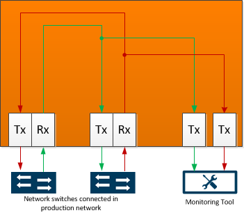
Tap a link with the G-TAP A-TX by disconnecting an existing link between two network devices (for example, the connection between an access switch and a distribution network) and reconnecting the link so that data flows through the tap (How to Use G-TAP A Series 1).

-
G-TAP A-TX Data Flow
To tap a link with the G-TAP A-TX:
-
Connect test traffic to the Network A/B ports, close the tap relays with the config taptx passive command, and verify that traffic flows through the tap as expected
-
After verifying traffic flow in passive mode, switch back to active mode with config taptx active.
-
Use show port-params to verify that speed, duplex, and link state are correct.
-
With passive mode successfully tested, you can connect the production link. Connect the Ethernet cable from one network device to the Network A port.
-
Connect another cable from the second network device to the Network B port, making sure not to exceed the maximum combined cable length of 100 meters.
- Connect the Monitor/Tool ports either to a network analysis tool or to a GigaVUE data access switch for intelligent distribution to multiple tools.
With the tap operating in Active mode, traffic is sent to the Monitor/Tool ports, as shown in How to Use G-TAP A Series 1. The G-TAP A-TX automatically closes its relays and switches back to passive mode if all primary power sources are lost and the backup battery drops to 15 percent of charge capacity.
Power Loss and the G-TAP A-TX
The A Series implements Gigamon’s unique Always-On architecture, eliminating network link downtime through the use of primary power sources and a secondary on-board battery backup. Primary power sources charge the backup battery when it is at 95 percent of capacity, so it is ready to assume the power load in the event of a power failure on the primary sources. Charging stops when the battery is at 100 percent capacity.
When all primary power sources are lost, the on-board battery takes over, maintaining operations for up to one hour. SNMP traps are generated at 25 percent increments as the available battery charge falls to - 75%, 50%, and 25%.
The last Battery Level % trap is the generated when the available battery charge falls to 15%. At this point, the system closes the tap relays and falls back to passive mode with traffic flowing only across the Network ports. Because of this, Gigamon recommends testing the tap in passive mode before deploying it on a production link.
Blinking Link LEDs on G-TAP A-TX?
When autonegotiation is enabled, the G-TAP A-TX attempts to negotiate speed/duplex settings with the devices connected to the Monitor/Tool ports matching those already negotiated with the devices on the Network ports.
If the G-TAP A-TX is not able to negotiate a matching speed with the devices connected to the Monitor/Tool ports, it indicates the speed mismatch by blinking the Link LEDs on the affected Monitor/Tool port.
The devices connected to the Monitor/Tool ports must be capable of operating with the same speed/duplex settings used on the Network ports for successful traffic flow.
Note: If the devices connected to the Network ports are forced to 100Mbps Full Duplex and the G-TAP has autonegotiation enabled, the G-TAP A-TX falls back to 100Mbps Half Duplex as required by autonegotiation standards.
Tap a Link with the G-TAP A-SF
Tap a link with the G-TAP A-SF by disconnecting an existing link between two network devices (for example, the connection between an access switch and a distribution network) and reconnecting the link so that data flows through the tap.
As shown in the following figure, G-TAP A-SF data flow is as follows:
- Packets received on Network Port A are sent out Monitor/Tool Port A.
- Packets received on Network Port B are sent out Monitor/Tool Port B.

Power Loss and the G-TAP A-SF
The A Series implements Gigamon’s unique Always-On architecture, eliminating network link downtime through the use of primary power sources and a secondary on-board battery backup. Primary power sources charge the backup battery when it is at 95 percent of capacity, so it is ready to assume the power load in the event of a power failure on the primary sources. Charging stops when the battery is at 100 percent capacity.
When all primary power sources are lost, the on-board battery takes over, maintaining operations for up to one hour. SNMP traps are generated at 25 percent increments as the available battery charge falls to - 75%, 50%, and 25%.
The last Battery Level % trap is the generated when the available battery charge falls to 15 percent. The G-TAP A-SF keeps traffic flowing as long as it can with the power available. However, once all power is exhausted, no traffic passes through the tap, either through the Network or Tool ports.
G-TAP A-SF Transceiver Notes and Rules
The G-TAP A-SF supports SFP (SX/LX/ZX) and SFP+ (SR/LR/ER/LRM) transceivers, as well as 1M and 5M Direct Attach Cables (SFP+ Copper) for connectivity to 1G/10G fiber and copper Ethernet links. For details on the transceivers supported for use with the G-TAP A-SF, refer to G-TAP A-SF Transceiver Details on page 43.
Keep in mind the following notes and rules for transceivers used with the G-TAP A-SF:
- Always use transceivers purchased from Gigamon to ensure interoperability and performance.
- Tap speed is determined by the external devices connected to the Network ports. The external devices must be running at the same speed for data to be passed to the Monitor/Tool ports.
-
Both Network ports must use the same transceiver type (for example, an SX SFP in Network A and an SX SFP in Network B).
-
The Tool port transceivers must support the same speed as the Network port transceivers. However, the Tool port transceivers do not need to be the same medium, either as one another or as those in the Network ports.
For example, if the network ports both use 1G multimode fiber transceivers, you could use a 1G single-mode fiber transceiver in Tool Port A and a 1G copper SFP transceiver in Tool Port B. This is summarized in the following table:
|
Network Port A |
Network Port B |
Tool Port A |
Tool Port B |
|---|---|---|---|
|
1G SFP MM |
1G SFP MM |
1G SFP SM |
1G SFP Copper |
- When using 1G SFP Optical Transceivers in the Monitor/Tool ports, the connected tools must have autonegotiation disabled for the link to establish successfully.
- Copper SFP transceivers can only be used at 1G speeds (1000BASE-T). There are no configurable autonegotiation, speed, or duplex settings for these transceivers that would allow 10/100 Mbps use.
Sample Transceiver Combinations
How to Use G-TAP A Series 1 lists some sample combinations of transceivers supported by the G-TAP A-SF. Note the following in each of these combinations:
- The Network Port transceivers always match both speed and medium.
- The Tool Port transceivers always run at the same speed as the Network Port transceivers. However, they do not necessarily need to match the medium either of the Network Port transceivers or of one another.
These are only samples – so long as the Network port transceivers match speed and medium and the tool oort transceivers can support the speed used by the external devices, the combination works. However, if the network port transceivers are using copper medium, the tool port transceivers must also use copper medium.
|
Transceiver Combinations for G-TAP A-SF |
|||
|---|---|---|---|
|
Network Port A |
Network Port B |
Tool Port A |
Tool Port B |
|
1G SFP Cu |
1G SFP Cu |
1G SFP Cu |
1G SFP Cu |
|
1G SFP MM |
1G SFP MM |
1G SFP MM |
1G SFP MM |
|
1G SFP SM |
1G SFP SM |
1G SFP SM |
1G SFP SM |
|
10G SFP MM |
10G SFP MM |
10G SFP MM |
10G SFP MM |
|
10G SFP SM |
10G SFP SM |
10G SFP SM |
10G SFP SM |
|
10G Direct Attach |
10G Direct Attach |
10GDirect Attach |
10GDirect Attach |
View Port Parameters
Use the show port-params command in the G-TAP A Series command-line interface to view the current settings used by the transceivers in the G-TAP A-SF Network and Monitor/Tool ports.
For example, the following sample CLI output shows matching SFP+ transceivers in the Network ports, while one Monitor/Tool port has an SFP and the other is empty:

Connect G-TAP A Series 1 to GigaVUE Visibility Node
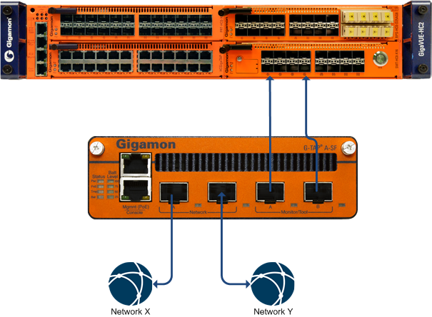
Connect the G-TAP A Series 1 to a GigaVUE traffic visibility node to take advantage of powerful GigaVUE traffic distribution features. You can connect any G-TAP A Series model to ports using matching media on a G or H Series GigaVUE traffic visibility node (fiber-to-fiber or copper-to-copper).
In this example, the Network A and Network B ports on the G-TAP A-SF are connected to ports on a module in a GigaVUE-HC2. Data passing through the G-TAP A Series is available for intelligent distribution throughout the Gigamon visibility fabric using standard GigaVUE packet distribution techniques (maps/xbmaps, connects/xbconnects, and pass-alls). In addition, traffic received on one Network port is actively regenerated out the other Network port.

Using the G-TAP with the Gigamon Visibility Fabric


